CROSS Technical Documentation User Manual and Technical Doc.
INFN Milano Bicocca
Loading...
Searching...
No Matches
Adc

ADC managing

SUMMARY:

On Board Adc usage


The ADC on board is the 24 bits AD7732BRU datasheet. It has some parameters that can be set with flags in its instruction. Its main function to be called is ADC_lettura(), whose code is the following:

710int32_t ADC_lettura(uint8_t scheda_su_scheda_giu_, uint8_t node_to_read, uint8_t cosa_fare){
711 //Da implementare: lettura di un qualsiasi nodo con ADC interno
712 status = SPIdrv->Control(SPI_control_for_relay_driver,spi_clock_for_relais);
713 if(scheda_su_scheda_giu_>1)scheda_su_scheda_giu_=1;
714 if( cosa_fare <=2){
715 //Si seleziona l'analog mux sulla mainboard, se serve
716 if ( (node_to_read >= node_voltage_Analog_Mux_0_offset ) ){//Questo \'e il mux della mainboard A
717 Analog_mux_line_to_select_deselect(scheda_su_scheda_giu_, node_to_read & 0xF, 1);
718 }
719 //si seleziona l'analog mux sulla postmainboard
720 Analog_mux_line_to_select_deselect_for_postmainboard ( scheda_su_scheda_giu_, node_to_read, 1 ) ;
721 //si toglie la res da 10k, questo viene fatto all'interno della funzione della lettura ADC
722 //si seleziona l' ADC
723 //si spara la misura in parallelo
724 ADC_misura_fatta = ADC_lettura_24bit( node_to_read, scheda_su_scheda_giu_, cosa_fare); //Lancio la misura con (2)(non in parallelo) o senza (1) polling
725 }
726
727 if ( cosa_fare ==3){
728 //si leggono solo gli ADC
729 ADC_misura_fatta = ADC_lettura_24bit( node_to_read, scheda_su_scheda_giu_, 3 );
730 }
731 if( cosa_fare>=2){
732 //Si de-seleziona l'analog mux sulla mainboard, se serve
733 if ( (node_to_read >= node_voltage_Analog_Mux_0_offset ) ){//Questo \'e il mux della mainboard A
734 Analog_mux_line_to_select_deselect(scheda_su_scheda_giu_, node_to_read & 0xF, 0);
735 }
736 //si de-seleziona l'analog mux sulla postmainboard
737 Analog_mux_line_to_select_deselect_for_postmainboard ( scheda_su_scheda_giu_, node_to_read, 0 ) ;
738 }
739// uint8_t numeratore=1, denominatore=1; //Attenuation is always 1 but with detector bias
740// if( (node_to_read >=node_voltage_Analog_Mux_0_offset) && (node_to_read <=(node_voltage_Analog_Mux_0_offset +14))){ //14=12 bias voltage + 2 external bias
741// numeratore=ADC_numeratore_Bias;
742// denominatore= ADC_denominatore_Bias;
743// }
744// ADC_misura_fatta = (ADC_misura_fatta *numeratore) / denominatore;
745// ADC_misura_fatta = (ADC_misura_fatta * ADC_coefficiente[node_to_read / ADC_molteplicita_node_to_read].numeratore )\
746// / ADC_coefficiente[node_to_read / ADC_molteplicita_node_to_read].denominatore ;
747
748 return ADC_misura_fatta;
749}
long int ADC_lettura_24bit(char line_to_read_to_select_ADCch0_ADCch1, uint8_t up_down, uint8_t cosa_fare)
ADC Wakeup and 24 bits reading.
Definition: Adc.c:433
int32_t ADC_lettura(uint8_t scheda_su_scheda_giu_, uint8_t node_to_read, uint8_t cosa_fare)
This function allows to read the voltage of any of the selectable nodes.
Definition: Adc.c:710
#define spi_clock_for_relais
[ref_spi_clock_for_relais]
void Analog_mux_line_to_select_deselect(uint8_t scheda_su_scheda_giu, uint8_t line_to_select, uint8_t select_1_deselect_0)
Selection of the line to mesure with the analog MUX of the mainboard, driven by the I2C->parallel mux...
void Analog_mux_line_to_select_deselect_for_postmainboard(uint8_t scheda_su_scheda_giu, uint8_t line_to_select, uint8_t select_1_deselect_0)
Selection of the line to measure with the analog MUX's of the postmainboard, directely driven by the ...
@ node_voltage_Analog_Mux_0_offset
Starting Offset for this set of nodes, 32.
#define SPI_control_for_relay_driver
[ref_SPI_control_for_relay_driver]
Definition: Spi.h:10


Reading result has to be multiplied by numeratore, then divided by denominatore. This to work with integer numbers: remember that our voltages are in µV.
Each node to be read has its own identity; as an instance, the detector bias is read after a voltage attenuator. The reading nodes are organized in groups of 6, there is a vector structure whose locations are retreived by node_number/6:

71 int16_t numeratore;
72 int16_t denominatore;
73};


Here is the vector ADC_coefficiente and here we see the coefficient values:


These number are exploited by the function ADC_compensazione_al_nodo() that needs as input parameters the node that is being measured by line_to_read. Then, from the ADc measured value, lettura_ADC and offset lettura_offset the actual node voltage is obtained. The above coefficiennts take into account the attanuator factors at the buffer inputs according to the following figure:

Figure_ADC_Buffeattenuation 1: ADC buffer in switchable resistor
Note
During the developing phase the board can be connected to an external ADC rather than that of the postfrontend, or mainboard B. Dscrimination between internal and external ADC can be made at the instruction level.

On Board ADC settings


At startup, within instr_inizializza_tutto_da_zero_function(), both ADC's are initialized. The first action done on ADC is the settings of its configuration pins. This is done at startup by the function ADC_pin_configurations(void). Soon after that the SPI protool is set, SPI_Inizialize(), the ADC's zero scale calibration is done, with ADC_selfcal_zero_scale(uint8_t up_down) invoked 2 times, one for each ADC present, than, the ADC's are sent into powerdown state with the function ADC_Sleep_fun(uint8_t up_down), invoked 2 times, too.

ADC Operation


The ADC functions list is here:


On the top of the above list there are the 2 functions that operate globally the ADC's to perform the measurement.
The first one is ADC_misura_differenziale_con_media_generico() that allows to set all the necessary parameters to perform the measurement. The user could use only this function to operate the ADC.
There are 2 parameters that are not passed to the function but are global and need to be set at least once, or their default values are considered.
The variable ADC_medie_per_misura is the first of the 2 variables that are not passed as a parameter but is a global. It can be set with the instruction via CAN, instr_ADC_LETTURA. It says to the function how many measurements of the node must be taken and averaged.
The other variable that is not passed, but is global is ADC_non_leggi_lo_offset_se_true. If it is true the input offset of the buffer which stands in front of the ADC is not read, Figure_ADC_Buffer_attenuation_input. With the new OA used the offset is very small and its measurement can be omitted. This shortens the reading time. This flag can be set ON or OFF from the instruction, instr_ADC_LETTURA.
The input parameters to the first function are:

  • scheda_su_scheda_giu_ is the board selection;
  • preamplifier_externalADC_1_onboardADC_0 indicates whether the ADC's on board are used or an external ADC is the selcted to perform the measurement, usually this parameter is set to zero since the external ADC is selected only for testing purpose;
  • nodo_da_misurare is the node whose voltage is to be measured, the node list can be found at lista nodi;
  • differenziale1_single_0 determines whether the measurement is performed differential os single ended. As an example, the ouput of the PGA amplifier is differential and we can read it as Vout_pos - Vout_neg , or to read Vout_pos and Vout_neg indipendently.


The second function, ADC_misura_differenziale_single_ended(), is invoked from the previous function. Its parameters are similar to the previous described above:

  • scheda_su_scheda_giu is the board from which volateg nodes must be read;
  • nodo_da_leggere is the node to be read according to lista nodi;
  • differenziale_1_single_0 determines whether the measurement is performed differential os single ended.


The function ADC_pin_configurations() is invoked just one time, at the startup. Calibration is done at startup, too, and can be invoked from time to time from the CAN, too.
ADC_Wakeup() is called every time a reading must be taken, while ADC_Sleep_fun() is invoked at the end of the reading function.
ADC_lettura_24bit(char ADC_0_o_1 , uint8_t up_down, uint8_t cosa_fare) allows a single reading of the previously selected node. It needs to know which of the 2 ADC channels to use with ADC_0_o_1, and which ADC to consider with up_down. The last parameter cosa_fare allows to operate the 2 ADC in parallel, if needed. It cover 3 values as it follows:

  • cosa_fare=1: The measurement is only started. The measurement function is not blocking and this allows to launch the measurement with the other ADC in parallel. The returned value is 0 in this case. Take care that the parallel operation is not possible with the 2 channels of the ADC because the ADC is multiplexed. If the parallel operation is anyway set for the 2 channels of the same ADC one measurement will be lost.
  • cosa_fare=2: In this case the measuremen is launched and the result is waited and returned. This is a situation for which parallel operation is not exploited. This function is blocking.
  • cosa_fare=3: In this case the result is waited of the measuremnt launched in a previous call with cosa_fare=1.

An example of parallel operation is here (cosa_fare=1 combined with cosa_fare=3):

//The 2 measurements have started in parallel and below here are read
int risultato[2];
#define I2C_mux_Scheda_giu
Selection of the I2C1 for lower board (purtroppo \'e contorto)
Definition: I2C_mux.h:16
#define I2C_mux_Scheda_su
Selection of the I2C0 for the upper board (purtroppo \'e contorto)
Definition: I2C_mux.h:15

An example of non parallel operation is here (cosa_fare=2):

int risultato[2];
//Now the second measurement below will be done just after the measurement
//above is finisched since now the function is blocking

The inputs of the ADCs are buffered. The input resistor of the buffer is a switchable, in principle. This feature cannot be used since the switches are MOS whos parasitic diode becomes forward bias when the input voltage goes negative. In this versione of the board the MOS are used for another fnctions and the resistirs is held to GND. Its value is not 10 KΩ, as in the picture below, but 82 KΩ; at the same time the resistor in series to the analog MUX's ouputs is now 8.2 KΩ. This combination attenuates a little the value of the input node to measure and avoid to be too close to the rails, where the accuracy of the buffer lowers a little.

Figure_ADC_Buffer_in 2: ADC buffer in switchable resistor

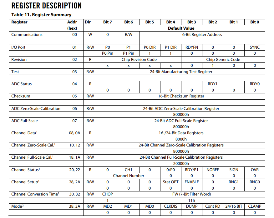
ADC_lettura_registro() allows to read a whatever ADC internal register of the selected ADC and ADC channel. Possible choices are (select the left number of the Addr column):

Figure_ADC_reg 3: ADC register MAP. Select the register number from the Addr column. In case 2 numbers are available, choose the left one.


ADC_lettura(uint8_t scheda_su_scheda_giu, uint8_t node_to_read, uint8_t cosa_fare) sets the path, from the node to read, to the ADC input. First of all scheda_su_scheda_giu determines the region to operate and the ADC to select. It needs to know the node(node_to_read) to set the path. Then cosa_fare is the parameter with which we can operate in parallel with the same sintax seen above.


Finally, instr_ADC_LETTURA_function(), is the function that is called when the CAN instruction is invoked, instr_ADC_LETTURA.

Off Board ADC


This option is anomalous becasue is the µ-controller that is asking back the requirement to read the node voltage. Through the CAN Bus and the ReadBack Node Voltage instruction any available node volatge can be read. The function that is able to perform this operation is:

712int32_t preamplifier_ADC_external_measured_node_function(uint8_t scheda_su_scheda_giu, uint8_t indice){
713 //richiedere sul CAN la misura
714 //In questo caso scheda su o gi\'u non ha importanza perch\'e l'ADC esterno sar\'a connesso direttamente ad una sola scheda
715 uint8_t ii=0;
716 int32_t valore_mis;
717 evento_CAN=10;
718 uint8_t buffer_istruzione[8],iii;
719 for(iii=0;iii<8;iii++){
720 buffer_istruzione[iii]=tx_data[iii];
721 }
722 if ( (indice >= node_voltage_Analog_Mux_0_offset ) ){
723 //Misura su uno dei 2 nodi dei mux
724 Analog_mux_line_to_select_deselect(scheda_su_scheda_giu, indice , 1);
725 }
726 tx_data[5]= indice; //The node to be measured, the code includes also the selected board
727 tx_data[6]= 1; //This must be "1" and says that the node voltage read must be returned here
728 tx_data[7]= instr_readback_node_voltages ; //instr code
729 tx_msg_info.id = ARM_CAN_EXTENDED_ID(indirizzo_CAN_della_scheda);
730 CANdrv->MessageSend(tx_obj_idx, &tx_msg_info, tx_data, 8U);//msg to CAN back to the control room
731 Aspetta_tanti_ms(100); //From here we wait the answer or generate an error
732 //Aspettare che la misura sia fatta, o generare errore
733 //! [CAN error marker]
734 //Before here a CAN message has been sent with success, we hope
735 while( (ii <50) && ( evento_CAN != ARM_CAN_EVENT_RECEIVE ) ){
736 Aspetta_tanti_ms(200);
737 ii++;
738 }
740 //! [CAN error marker]
741 if( (indice >= node_voltage_Analog_Mux_0_offset ) ){
742 //Reset di uno dei 2 mux usati per la misura
743 Analog_mux_line_to_select_deselect(scheda_su_scheda_giu, indice , 0);
744 }
745
746 valore_mis= ( ( ( *(int32_t *)rx_data ) & 0xFFFFFFFF ) ) ;
747 //Convertiamo in funzione del nodo dal leggere
748 valore_mis = (valore_mis * ADC_coefficiente[indice / ADC_molteplicita_node_to_read].numeratore )\
749 / ADC_coefficiente[indice / ADC_molteplicita_node_to_read].denominatore ;
750 for(iii=0;iii<8;iii++){
751 tx_data[iii]=buffer_istruzione[iii];
752 }
753 return valore_mis; //The value returned is the voltage in microV
754}
const struct ADC_coefficiente_type ADC_coefficiente[]
Node normalizing coeficinets used in ADC_lettura_24bit()
Definition: Adc.c:210
#define ADC_molteplicita_node_to_read
Definition: Adc.h:64
@ instr_readback_node_voltages
Nodes voltage read from external ADC.
uint8_t tx_data[8]
Transmission data vector.
Definition: Can.c:321
uint32_t volatile evento_CAN
This is the variable which resembles the flags from the communication.
Definition: Can.c:326
uint32_t tx_obj_idx
This is the variable which resembles the flags from the communication.
Definition: Can.c:323
unsigned int indirizzo_CAN_della_scheda
Per ora lo assegnamo cos\i l'indirizzo della scheda.
Definition: Can.c:335
volatile uint8_t rx_data[8]
Received data vector.
Definition: Can.c:318
ARM_DRIVER_CAN * CANdrv
Definition: Can.c:333
void ERROR_codifica_errore(uint8_t scheda_su_scheda_giu, unsigned char error_addres, unsigned char code_to_shift, uint8_t reset_count_se_0)
If an error is found its flag is codified here.
@ CAN_error_comunichiamo_qualche_dato_timeout_on_transmission
Transmission CAN error.
@ error_address_CAN
Error register for CAN bus
int32_t preamplifier_ADC_external_measured_node_function(uint8_t scheda_su_scheda_giu, uint8_t indice)
This function provide node reading from an external ADC.
void Aspetta_tanti_ms(int millisecondi)
The timing function.
Definition: Timer.c:52

Conclusions


This section must be expanded


The codes for mamnaging the ADC are: