CROSS Technical Documentation User Manual and Technical Doc.
INFN Milano Bicocca
Loading...
Searching...
No Matches
Trimmer

Trimmer managing

SUMMARY:

Trimmer usage


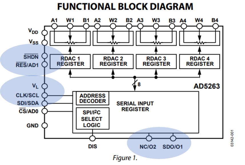
Trimmers are used for setting the detector bias, the preamplifier offset and the preamplifier thermal drift and the gain of the trimmer based PGA. The trimmer used is the AD5263 datasheet, a quad trimmer whose schematic diagram is in figure Figure_Trimmer_AD5263_trimmer. To manage the stuffs we have 3 main functions, quite similar: preamplifier_scrittura_lettura_trimmer(uint8_t scheda_su_scheda_giu, uint8_t canale, uint8_t trimmer, uint8_t valore, uint8_t scrivi_1_leggi_0 ), detector_scrittura_lettura_trimmer_bias(uint8_t scheda_su_scheda_giu, uint8_t canale, uint8_t trimmer, uint8_t valore, uint8_t scrivi_1_leggi_0) and trimmer_based_PGA(). We have a sort of tree: it needs to identify the board, the channel, the trimmer and the value to write, if we need to write, otherwise we read the content; reading writing is established with the boolean scrivi_1_leggi_0.
For detector and preamplifier the 4 trimmers of the chip have different functions. For what concern the preamplifier we have that (the bullet number is the addresss inside the chip):

  1. trimmer_CMRR_compensation;
  2. trimmer_fine_offset;
  3. trimmer_thermal_compensation;
  4. trimmer_coarse_offset.

Whereas for detector trimmer:

  1. Detector_trimmer_coarse_bias_pos
  2. Detector_trimmer_coarse_bias_neg
  3. Detector_trimmer_fine_bias_pos
  4. Detector_trimmer_fine_bias_neg


The content of every trimmer is stored in matrixes: contenuto_trimmer_detector, contenuto_trimmer_preamplifier and contenuto_trimmer_PGA_a_trimmer. They are listed here with their default values:

uint8_t contenuto_trimmer_detector[12][4]={ 128, 128, 128, 128, //!< Scheda gi\'u
128, 128, 128, 128,
128, 128, 128, 128,
128, 128, 128, 128,
128, 128, 128, 128,
128, 128, 128, 128,
128, 128, 128, 128, ///< Scheda su
128, 128, 128, 128,
128, 128, 128, 128,
128, 128, 128, 128,
128, 128, 128, 128,
128, 128, 128, 128};///< Detetctor bias trimmer content. Default value is half scale
uint8_t contenuto_trimmer_detector[12][4]
Content of the trimmer for detector bias system.
Definition: Trimmer.c:161
uint8_t volatile contenuto_trimmer_preamplifier[12][4]={ 128, 128, 128, 128, //Scheda gi\'u
128, 128, 128, 128,
128, 128, 128, 128,
128, 128, 128, 128,
128, 128, 128, 128,
128, 128, 128, 128,
128, 128, 128, 128, //Scheda su
128, 128, 128, 128,
128, 128, 128, 128,
128, 128, 128, 128,
128, 128, 128, 128,
128, 128, 128, 128}; ///< Preamplifier trimmers contents
uint8_t volatile contenuto_trimmer_preamplifier[12][4]
Definition: Trimmer.c:179

For the caseof the trimmer based PGA the number of trimmers used for the 12 channles is 6, one every 2 channels:

uint8_t volatile contenuto_trimmer_PGA_a_trimmer[6][4]={ 245, 245, 245, 245, //Scheda gi\'u
245, 245, 245, 245,
245, 245, 245, 245,
245, 245, 245, 245, //Scheda su
245, 245, 245, 245,
245, 245, 245, 245}; ///< PGA a trimmer trimmers contents
uint8_t volatile contenuto_trimmer_PGA_a_trimmer[6][4]
Definition: Trimmer.c:206

FigureTrimmer_AD5263: simplified


Although not necessary for its direct usage, let's give a bit of further details. Every trimmer chip is selectd by mean of a constant struct with which it is possible to select both the I2C and its I2C address:

uint8_t quale_I2C; //<! One of the 4 the I2C mux
uint8_t indirizzo_I2C; //<! Device address
};
Coordinates for the preamplifier and onboard EPROMs.
Definition: Trimmer.h:97

First of all the I2C, the I2C mux and which of the 4 I2C mux output channels must be selcted with I2C_mux_select_ch( uint8_t scheda_su_scheda_giu, uint8_t mainboard_postmainboard , uint8_t canale_da_abilitare)

A few details about the functions


We have the 2 constant structures for trimmer selection address_detector_bias_trimmer and address_preamplifier_trimmer. The structures are used within the functions preamplifier_scrittura_lettura_trimmer() and detector_scrittura_lettura_trimmer_bias(). Here an example:

void detector_scrittura_lettura_trimmer_bias(uint8_t scheda_su_scheda_giu, uint8_t canale, uint8_t trimmer, uint8_t valore, uint8_t scrivi_1_leggi_0 ){
//Attenzione: canale deve essere < 6
uint8_t spedizione[2]={ ( (trimmer << 5) & maschera_solo_bit_di_scrittura_trimmer), valore}; //The trimmer and what to write
if( scheda_su_scheda_giu) scheda_su_scheda_giu =6;
I2C_mux_select_ch( scheda_su_scheda_giu, I2C_mainboard, address_detector_bias_trimmer[canale].quale_I2C); //Select the I2C to be used
if (scrivi_1_leggi_0){
I2C_mux->MasterTransmit( (uint8_t) address_detector_bias_trimmer[canale].indirizzo_I2C , spedizione, 2,false); //Write to the selected trimmer of the selcted channel
}else{
I2C_mux->MasterTransmit( (uint8_t) address_detector_bias_trimmer[canale].indirizzo_I2C , spedizione, 1,false); //set the channel to read only
}
while( I2C_mux->GetStatus().busy){}; // Write transmission complete
I2C_mux->MasterReceive( address_detector_bias_trimmer[canale].indirizzo_I2C, &tappo, 1,false); //Read back, the trimmer value
while( I2C_mux->GetStatus().busy){};
contenuto_trimmer_detector[canale + scheda_su_scheda_giu][trimmer] = tappo; //Tappo is global
}
volatile uint32_t Error_bad_operation
exploited to mark the errors
void ERROR_codifica_errore(uint8_t scheda_su_scheda_giu, unsigned char error_addres, unsigned char code_to_shift, uint8_t reset_count_se_0)
If an error is found its flag is codified here.
@ I2C_error_trimmer_bias_0
trimmer_bias ch0
@ error_address_I2C1_B
Error register B for I2C1
void I2C_mux_select_ch(uint8_t scheda_su_scheda_giu, uint8_t mainboard_postmainboard, uint8_t canale_da_abilitare)
The I2C mux.
Definition: I2C_mux.c:100
const struct address_detector_bias_trimmer_type address_detector_bias_trimmer[6]
Detector trimmer addresses.
Definition: Trimmer.c:129
void detector_scrittura_lettura_trimmer_bias(uint8_t scheda_su_scheda_giu, uint8_t canale, uint8_t trimmer, uint8_t valore, uint8_t scrivi_1_leggi_0)
Setting the value of any trimmer for detector biasing, the contents of the trimmers are stored in the...
Definition: Trimmer.c:238
#define maschera_solo_bit_di_scrittura_trimmer
Mask for command of the trimmer.
Definition: Trimmer.h:76

Preamplifier Slope measurement


Offset regulation of preamplifier is based on 2 trimmers, a coarse and fine trimmer. The adjustment can be done by SAR tecnique or by setting the propoer value of the trimmers, if it is known their effects. The in-between solution is to set the value of the trimmers at a guess value, then use the SAR for a few bits. The function is quite long and reported here instr_offset_trimmer_calibration_function().


Once that the slope has been measured it is stored in the preamplifier EPROM. The 2 slopes are stored at 2 locations preceded by a location that says if the slopes have been characterized (the complete list is at Preamplifier EPROM location list):

  1. Memory_preamplifier_slope_calibration_ON_0_OFF_ff;
  2. Memory_preamplifier_address_fine_trimmer_slope_offset;
  3. Memory_preamplifier_address_coarse_trimmer_slope_offset;


Namely if Memory_preamplifier_slope_calibration_ON_0_OFF_ff is 0xFF, the initial default, the following 2 locations are not usable because not set. If Memory_preamplifier_slope_calibration_ON_0_OFF_ff is 0, then the 2 following location have been characterized and are usable. In this latter case the slopes stored could be either the actual value measured or the nominal value if, during characterizatin, the measured values resulted outside ± 20% of tolerance with respect to the nominla value.

Conclusion


Refer to Detector Bias and Preamplifier Offset Drift Correcttion for trimmer usage.

The code for mamnaging the trimmers is at: