CROSS Technical Documentation User Manual and Technical Doc.
INFN Milano Bicocca
Loading...
Searching...
No Matches
I2C EPROM memory

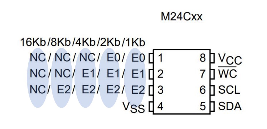
This chip is exploited to store the preamplifier parameters and settings

SUMMARY:

Use of the Preamplifier EPROM memory


Each unit of the system has its own EPROM memory where to store at least its sn and, when present, the fw version. The first samples of the preamplifier has the MC24C08, that is a 8 Kb I2C flash memory. The frontend board has a MC24C16. Finally the postfrontend board has the MC24C64. The different memory sizes have different cell address organization. From 1Kb up to 16Kb they are shown in figure Figure_M24C00_16K. Namely, depending on the size, the 8-LSb bits are in the first word sent, while the MSb in excess of 8 are in the first bits of the I2C addres, so that the larger is the size, the lesser is the available choice left for the I2C addres (4 of the 7 I2C address bits are fixed). Different is the approach for the M24C32 and M24C64 that uses 2 bytes of data for addressing and have the 3 available bits free for I2C address, the case 1 KB in Figure_M24C00_16K.
In our frontend we are going to use the M24C32 for both the preamplifier and the frontend board and the M24C64 in the post frontend board. The different choices are only due to the availability at the moment of the population of the boards. Both memories requires a 2-bytes address.
An example of use of 4-bytes writing of the 32k/64K EPROM at addres 0x20 of the channel6 EPROM is here:

dati_da_scrivere[0]= 50; // The value is arbitrary
dati_da_scrivere[1]= 60;
dati_da_scrivere[2]= 70;
dati_da_scrivere[3]= 80;
EPROM_scrittura_M24C32_64(scheda_su_scheda_giu_provvisorio, I2C_mainboard,, canale6 , 0x20 , dati_da_scrivere);
void EPROM_scrittura_M24C32_64(uint8_t scheda_su_scheda_giu, uint8_t mainboard_postmainboard, uint8_t canale, short indirizzo_memoria, uint8_t *dati_da_scrivere)
Wriring the EEPROM.

Figure_M24C00_16K 1: M24C00_16K I2C address organization

br


There are a number of variables and definitions to manage the memories, but the the functions to use are only 2 and very simple. To read from the memory we use EPROM_lettura_M24C32_64(uint8_t scheda_su_scheda_giu,uint8_t I2C_mainboard,uint8_t canale, short indirizzo_memoria , uint8_t *dati_letti), while to write EPROM_scrittura_M24C32_64(uint8_t scheda_su_scheda_giu, uint8_t mainboard_postmainboard , uint8_t canale, short indirizzo_memoria , uint8_t *dati_da_scrivere).
scheda_su_scheda_giu is one of the 2 boards to select, canali is the preamplifier memory or the frontend board memory, according to the following enum canali_eprom:

canale1,
canale2,
canale3,
canale4,
canale5,
canale6,
Canale_Eprom_mainboard,
Canale_EPROM_postmainboard_down,
Canale_EPROM_postmainboard_up};
canali_eprom
Refer to these definitions for using the channels during eprom R/W.


indirizzo_memoria is the address of the memory to write to or to read from and *dati_da_scrivere the pointer to the data to read/write. Take care: only 4 bytes can be read or written for each call.

Remarks
The EPROM is organized per pages whose length is 16 Bytes from sizes from 0 Kb up to 16 Kb, while it is 32 Bytes for the 32 Kb and 64 Kb. Writing can be done only per single page, namely, a writing cannot cover 2 pages contemporary. To avoid loss of data during writing in the stream of data the address bits from A4 to the MSb must not change, for EPROM size smaller or equal to 16 Kb. The same applies to the 32 Kb and 64 Kb except that in this case bits from A5 to the MSb are those that should not change during a data storage.
Note
Variables stored into the memories are located at fixed defined positions. To have a copy of them the .h files for the preamplifirs EPROM is the "enum preamplifier_EPROM" on the following link: Memoria_pre_M24CXX.h. Note that each element of the link must be multiplied by 4 for getting the actual address since the memory is orhanized as a uint32.

Channel state store and recovery


The state condition of the channel cane be recordered and aplied in a differenta ways. The variables that reflect the state are stored in 2 memory loactions.
The first state is that recalled at startup. This state requires that the PGA gain is 1 and that the preamplifier is connected to GND. The memory location for this state is Memory_preamplifier_startup_offset_trimmer. Note that at sturtup this state is applied only if the memory location Memory_preamplifier_startup_offset_trimmer_ON_0_OFF_ff is set to 0 value. This is done by the sw at the time the storing takes place. The state can be called also by setting the corresponding bit, but take care that for this case gain and detector state are not resumed and the user must do it. The startup state is created at the end of the offset adjustment, if the corresponding flag is set.
Another possible state is the user state. In this case it is stored at Memory_preamplifier_user_offset_trimmer and Memory_preamplifier_user_detector_and_gain which reflect the full condition for the channel, both offset, gain and detector condition. This state can be stored in 2 ways. After offset adjustment by setting the corresponding bit, or by a picture of the state, with no other actions than the storing of the variables, by setting the corresponding bit.
The state can be recovered by the corresponding bit and this work only if the Memory_preamplifier_user_offset_trimmer_ON_0_OFF_ff was set to 0. This is done by the sw at the time the storing takes place.
The bits to set are in the instr_output_offset_to_be_set, at the Byte3 option.

Remarks
If the startup stored is invoked remember that it refers to a PGA gain of 1 V/V and the detector disconnected. If the user state stored is invoked all the channel settings are recovered from memory: offset, PGA gain end detector settings. Regarding the detector setting the amount of the external bias, if it that consodered is not set.


The function invoked is the following:

527void EPROM_store_recover_state_M24C32_64(uint8_t scheda_su_scheda_giu,uint8_t canali_da_regolare, \
528uint8_t set_1_store_0 , uint8_t startup_1_user_0){
529
530 uint8_t dati_da_leggere[4],ii_,canale,dati_da_scrivere[]={0,0,0,0},esegui=0;
531 uint16_t memoria_per_trimmer, memoria_per_abilitazione, memoria_per_relay_PGA,memoria_per_detector_trimmer;
532 if(scheda_su_scheda_giu) scheda_su_scheda_giu=6;
533
534 if( startup_1_user_0){
535 memoria_per_abilitazione=Memory_preamplifier_startup_offset_trimmer_ON_0_OFF_ff <<2 ;
536 memoria_per_trimmer=Memory_preamplifier_startup_offset_trimmer <<2;
537 memoria_per_relay_PGA=0;
538 esegui=1;
539 }else if(startup_1_user_0 ==0){
540 memoria_per_abilitazione=Memory_preamplifier_user_offset_trimmer_ON_0_OFF_ff <<2;
541 memoria_per_trimmer=Memory_preamplifier_user_offset_trimmer <<2;
542 memoria_per_detector_trimmer=Memory_preamplifier_user_detector_trimmer;
543 memoria_per_relay_PGA = Memory_preamplifier_user_detector_and_gain <<2;
544 esegui=1;
545 }
546
547 if ((set_1_store_0 ==0) && esegui){ //Quindi scriviamo
548 for(canale=0;canale<6;canale++){
549 if((canali_da_regolare >> canale) &1 ){
550 EPROM_scrittura_M24C32_64(scheda_su_scheda_giu, I2C_mainboard,canale,\
551 memoria_per_abilitazione , dati_da_scrivere);
552 EPROM_scrittura_M24C32_64(scheda_su_scheda_giu, I2C_mainboard, canale,\
553 memoria_per_trimmer , (uint8_t *)&contenuto_trimmer_preamplifier[canale+scheda_su_scheda_giu]);
554 if (memoria_per_relay_PGA){
555 dati_da_scrivere[0]= detector_Relay_state[scheda_su_scheda_giu + canale];
556 dati_da_scrivere[1]= PGA_settled_gain[scheda_su_scheda_giu+canale];
557 dati_da_scrivere[2]= 0;
558 dati_da_scrivere[3]= 0;
559 EPROM_scrittura_M24C32_64(scheda_su_scheda_giu, I2C_mainboard,canale, \
560 memoria_per_relay_PGA , dati_da_scrivere);
561 dati_da_scrivere[0]= 0;
562 dati_da_scrivere[1]= 0;
563 EPROM_scrittura_M24C32_64(scheda_su_scheda_giu, I2C_mainboard,canale,\
564 memoria_per_detector_trimmer , (uint8_t *)&contenuto_trimmer_detector[canale+scheda_su_scheda_giu]);
565 }
566 }
567 }
568 }
569
570 if (set_1_store_0 && esegui){ //Quindi recuperiamo ed applichiamo o stato
571 for(canale=0;canale<6;canale++){
572 if((canali_da_regolare >> canale) &1 ){
573 EPROM_lettura_M24C32_64(scheda_su_scheda_giu, I2C_mainboard, canale, \
574 memoria_per_abilitazione , dati_da_leggere);
575 if(*(uint32_t *)dati_da_leggere ==0){
576 EPROM_lettura_M24C32_64(scheda_su_scheda_giu, I2C_mainboard, canale, \
577 memoria_per_trimmer , dati_da_leggere);
578 for(ii_=0;ii_<4;ii_++){
579 preamplifier_scrittura_lettura_trimmer( scheda_su_scheda_giu, canale, ii_, \
580 dati_da_leggere[ii_], preamplifier_scrivi_il_trimmer );
581 }
582 if(memoria_per_relay_PGA){
583 EPROM_lettura_M24C32_64(scheda_su_scheda_giu, I2C_mainboard, canale, \
584 memoria_per_relay_PGA , dati_da_leggere);
585 PGA_GAIN_CROSS( scheda_su_scheda_giu, canale, dati_da_leggere[1] );
586 for(ii_=0;ii_<7;ii_++){
587 if( (dati_da_leggere[0] >> ii_) & 1){
588 Relays_driver_set_reset_channel(scheda_su_scheda_giu,canale, (1<<ii_));
589 }
590 }
591 EPROM_lettura_M24C32_64(scheda_su_scheda_giu, I2C_mainboard, canale, \
592 memoria_per_detector_trimmer , dati_da_leggere);
593 for(ii_=0;ii_<4;ii_++){
594 detector_scrittura_lettura_trimmer_bias( scheda_su_scheda_giu, canale, ii_, \
595 dati_da_leggere[ii_], preamplifier_scrivi_il_trimmer );
596 }
597 }
598 }
599 }
600 }
601
602 }
603}
void PGA_GAIN_CROSS(uint8_t scheda_su_scheda_giu, uint8_t canale, uint8_t PGA_gain_to_set)
Here the 2 digital signals from the trimmer are exploited to set the gain of the input stage of the P...
Definition: DAC_PGA.c:109
uint8_t PGA_settled_gain[12]
PGA set gain.
Definition: DAC_PGA.c:95
uint8_t detector_Relay_state[12]
The state of the Detector realis is considerede. Note that this is the wanted working condition....
void Relays_driver_set_reset_channel(uint8_t scheda_su_giu, uint8_t numero_canale, uint8_t valore_da_trasmettere)
Setting the state of the detector realis: pre connected to detector or intrnal resistor,...
void EPROM_lettura_M24C32_64(uint8_t scheda_su_scheda_giu_, uint8_t mainboard_postmainboard, uint8_t canale, short indirizzo_memoria, uint8_t *dati_letti)
Read from preamplifier and on-board flashes.
void EPROM_store_recover_state_M24C32_64(uint8_t scheda_su_scheda_giu, uint8_t canali_da_regolare, uint8_t set_1_store_0, uint8_t startup_1_user_0)
Store the system state or recover and apply the system state.
@ Memory_preamplifier_user_detector_trimmer
detector trimmer content is stored here
@ Memory_preamplifier_startup_offset_trimmer
startup offset trimmer active if zero
@ Memory_preamplifier_user_offset_trimmer_ON_0_OFF_ff
user offset trimmer active if zero
@ Memory_preamplifier_startup_offset_trimmer_ON_0_OFF_ff
startup offset trimmer active if zero
@ Memory_preamplifier_user_offset_trimmer
startup offset trimmer active if zero
@ Memory_preamplifier_user_detector_and_gain
detectro setup anf PGA gain at user location
#define preamplifier_scrivi_il_trimmer
uint8_t contenuto_trimmer_detector[12][4]
Content of the trimmer for detector bias system.
Definition: Trimmer.c:161
void detector_scrittura_lettura_trimmer_bias(uint8_t scheda_su_scheda_giu, uint8_t canale, uint8_t trimmer, uint8_t valore, uint8_t scrivi_1_leggi_0)
Setting the value of any trimmer for detector biasing, the contents of the trimmers are stored in the...
Definition: Trimmer.c:238
uint8_t volatile contenuto_trimmer_preamplifier[12][4]
Definition: Trimmer.c:179
void preamplifier_scrittura_lettura_trimmer(uint8_t scheda_su_scheda_giu, uint8_t canale, uint8_t trimmer, uint8_t valore, uint8_t scrivi_1_leggi_0)
Setting the value of any trimmer for preamplifier trimmer, the contents of the trimmers are stored in...
Definition: Trimmer.c:283


Functions and vars details


Concerning the functions which are able to work with the EPROM having size smaller or equalt o 16Kb we have that the reading function is here:

483void EPROM_lettura_M24C32_64(uint8_t scheda_su_scheda_giu_, uint8_t mainboard_postmainboard, uint8_t canale, \
484 short indirizzo_memoria , uint8_t *dati_letti){
485 uint8_t tampone_qui=100,error_I2C;
486// uint8_t indirizzi_I2C=EPROM_address[canale].indirizzo_I2C;
487// indirizzo_memoria = indirizzo_memoria & 0xFFFC; //4 bytes at a time and composed of 2 bytes
488 dati_letti[1]= (indirizzo_memoria & 0xFF); //first 2 bytes are the 8 LSB bits sent as data
489 dati_letti[0]=( (indirizzo_memoria >> 8) & 0xFF); //first 2 bytes are the 8 LSB bits sent as data
490
491// indirizzi_I2C |= (indirizzo_memoria & 0x300)>>8 ; //I primi 2 bit nel secondo byte sono indirizzo
492
493 if(mainboard_postmainboard == I2C_mainboard){ //memoria su postmainboard o mainboard
494 tampone_qui=I2C_mainboard;
495 error_I2C =error_address_I2C1 ;
496 }else if (mainboard_postmainboard == I2C_postmainboard){
497 tampone_qui=I2C_postmainboard;
498 error_I2C = error_address_I2C0 ;
499 }
500 if (tampone_qui<100){ //Memory read
501 I2C_mux_select_ch( scheda_su_scheda_giu_, tampone_qui, EPROM_address[canale].quale_I2C);
502 I2C_mux->MasterTransmit (EPROM_address[canale].indirizzo_I2C, dati_letti , 2, false); //Scriviamo l'indirizzo iniziale
503 while (I2C_mux->GetStatus().busy);
504 if(Error_bad_operation) ERROR_codifica_errore( scheda_su_scheda_giu, error_I2C , I2C_error_EPROM_0 + canale , 1 );
505 I2C_mux-> MasterReceive (EPROM_address[canale].indirizzo_I2C, dati_letti, 4, false); //Ora leggiamo
506 while (I2C_mux->GetStatus().busy);
507 I2C_mux_select_ch( scheda_su_scheda_giu_, tampone_qui, I2C_mux_disabilita_tutto);
508 if(Error_bad_operation) ERROR_codifica_errore( scheda_su_scheda_giu, error_I2C , I2C_error_EPROM_0 + canale , 1 );
509 }
510
511}
volatile uint32_t Error_bad_operation
exploited to mark the errors
void ERROR_codifica_errore(uint8_t scheda_su_scheda_giu, unsigned char error_addres, unsigned char code_to_shift, uint8_t reset_count_se_0)
If an error is found its flag is codified here.
@ I2C_error_EPROM_0
EPROM ch0.
@ error_address_I2C0
Error register A for I2C0.
@ error_address_I2C1
Error register A for I2C1
void I2C_mux_select_ch(uint8_t scheda_su_scheda_giu, uint8_t mainboard_postmainboard, uint8_t canale_da_abilitare)
The I2C mux.
Definition: I2C_mux.c:100
#define I2C_mux_disabilita_tutto
i2C transmission/reception was bad
Definition: I2C_mux.h:24
const struct address_detector_bias_trimmer_type EPROM_address[9]
This is the structure from which the I2C addressess and the I2C of the preamplifier and frontend boar...


While the writng function is here:

435void EPROM_scrittura_M24C32_64(uint8_t scheda_su_scheda_giu, uint8_t mainboard_postmainboard, uint8_t canale, short indirizzo_memoria , uint8_t *dati_da_scrivere){
436
437// uint8_t Indirizzo_I2C_effettivo = (indirizzo_memoria & 0x3FF) >>8 ; //< The 2 MSB of the address memory are the
438 //first 2 bits of the I2C address
439// uint8_t indirizzo_memoria_8LSB= indirizzo_memoria & 0xFF;
440 uint8_t dati_da_spedire[6], tampone_qui=100, error_I2C;
441
442 dati_da_spedire[1]=indirizzo_memoria & 0xFF; //< this is the 8 LSb of the memory address
443 dati_da_spedire[0]=( indirizzo_memoria >> 8) & 0xFF; //< this is the 8 MSb of the memory address
444 dati_da_spedire[2]=dati_da_scrivere[0]; //<First data to store
445 dati_da_spedire[3]=dati_da_scrivere[1]; //<Second data to store
446 dati_da_spedire[4]=dati_da_scrivere[2]; //<Third data to store
447 dati_da_spedire[5]=dati_da_scrivere[3]; //<Fourth data to store
448
449// Indirizzo_I2C_effettivo += EPROM_address[canale].indirizzo_I2C;
450 if(mainboard_postmainboard == I2C_mainboard){ //memoria su postmainboard o mainboard
451 tampone_qui=I2C_mainboard;
452 error_I2C= error_address_I2C1;
453 }else if (mainboard_postmainboard == I2C_postmainboard){
454 tampone_qui=I2C_postmainboard;
455 error_I2C= error_address_I2C0;
456 }
457 if (tampone_qui<100){
458 I2C_mux_select_ch( scheda_su_scheda_giu, tampone_qui, EPROM_address[canale].quale_I2C);
459 I2C_mux->MasterTransmit (EPROM_address[canale].indirizzo_I2C, dati_da_spedire , 6, false); //Scriviamo l'indirizzo iniziale
460 while (I2C_mux->GetStatus().busy);
461 if(Error_bad_operation) ERROR_codifica_errore( scheda_su_scheda_giu, error_I2C , I2C_error_EPROM_0 + canale , 1 );
462 Aspetta_tanti_ms(10); //Attenzione, se non si temporeggia qui si blocca tutto.
463 I2C_mux_select_ch( scheda_su_scheda_giu, tampone_qui, I2C_mux_disabilita_tutto);
464 }
465}
void Aspetta_tanti_ms(int millisecondi)
The timing function.
Definition: Timer.c:52


There are 4 different I2C channels (selected at I2C_mux_select_ch()) and 2 I2C addresses are exploitable for the preamplifier EPROMs: EPROM_I2C_addres_memory_ch_pari and EPROM_I2C_addres_memory_ch_dispari, while the onboard EPROM is at EPROM_mainboard_I2C_addres. The I2C paremeters for each EPROM are in the structure address_detector_bias_trimmer_type:

//struct address_detector_bias_trimmer_type {
// uint8_t quale_I2C;
// uint8_t indirizzo_I2C;
//};


So that the 7 positions strucure is EPROM_address.


The codes for I2C_0 is at:

The list of locations of the preamplifier EPROM


Here the list of the locations of preamplifier EPROM, remember to multiply by 4, or <<2, the bullet number to set the actual address, an unsigned int:

  1. Memory_preamplifier_address_SN;
  2. Memory_preamplifier_slope_calibration_ON_0_OFF_ff;
  3. Memory_preamplifier_address_fine_trimmer_slope_offset;
  4. Memory_preamplifier_address_coarse_trimmer_slope_offset;

  5. Memory_preamplifier_startup_offset_trimmer_ON_0_OFF_ff;
  6. Memory_preamplifier_startup_offset_trimmer;
  7. Memory_preamplifier_user_offset_trimmer_ON_0_OFF_ff;
  8. Memory_preamplifier_user_offset_trimmer;
  9. Memory_preamplifier_user_detector_and_gain;
  10. Memory_preamplifier_user_detector_trimmer;

  11. Memory_detector_coarse_slope_calibration_ON_0_OFF_ff;
  12. Memory_detector_positive_address_coarse_trimmer_slope_bias;
  13. Memory_detector_negative_address_coarse_trimmer_slope_bias;
  14. Memory_detector_fine_slope_calibration_ON_0_OFF_ff;
  15. Memory_detector_positive_address_fine_trimmer_slope_bias;
  16. Memory_detector_negative_address_fine_trimmer_slope_bias.

  17. Memory_preamplifier_drift_ON_0_OFF_ff,
  18. Memory_preamplifier_trimmers_for_drift,
  19. Memory_preamplifier_offset_slope_trimmer_with_temp
  20. Memory_preamplifier_compensation_slope_trimmer_with_temp
  21. Memory_preamplifier_compensation_slope
  22. Memory_preamplifier_last_memory_used_first_free

The last memory cell used is #Memory_preamplifier_last_memory_used. If it not coincide with the length of the list above it means that the list is not upgraded.

The list of locations of the mainboard EPROM adrress


Here the list of the locations of mainboard EPROM, remember to multiply by 4, or <<2, the bullet number to set the actual address, an unsigned int:

  1. Memory_mainboard_address_SN;

  2. Memory_mainboard_address_fw;
  3. Memory_mainboard_address_CAN_own_filter;
  4. Memory_mainboard_address_CAN_common_filter;

  5. Memory_mainboard_preamplifier_address_SN_0;
  6. Memory_mainboard_preamplifier_address_SN_1;
  7. Memory_mainboard_preamplifier_address_SN_2;
  8. Memory_mainboard_preamplifier_address_SN_3;
  9. Memory_mainboard_preamplifier_address_SN_4;
  10. Memory_mainboard_preamplifier_address_SN_5;

  11. Memory_mainboard_det_coa_slope_cali_ON_0_OFF_ff_ch0;
  12. Memory_mainboard_det_positive_ad_coarse_trim_slope_bias_ch0;
  13. Memory_mainboard_det_negative_ad_coarse_trim_slope_bias_ch0;
  14. Memory_mainboard_det_fin_slope_cali_ON_0_OFF_ff_ch0;
  15. Memory_mainboard_det_positive_ad_fine_trim_slope_bias_ch0;
  16. Memory_mainboard_det_negative_ad_fine_trim_slope_bias_ch0;

  17. Memory_mainboard_det_coa_slope_cali_ON_0_OFF_ff_ch1;
  18. Memory_mainboard_det_positive_ad_coarse_trim_slope_bias_ch1;
  19. Memory_mainboard_det_negative_ad_coarse_trim_slope_bias_ch1;
  20. Memory_mainboard_det_fin_slope_cali_ON_0_OFF_ff_ch1;
  21. Memory_mainboard_det_positive_ad_fine_trim_slope_bias_ch1;
  22. Memory_mainboard_det_negative_ad_fine_trim_slope_bias_ch1;

  23. Memory_mainboard_det_coa_slope_cali_ON_0_OFF_ff_ch2;
  24. Memory_mainboard_det_positive_ad_coarse_trim_slope_bias_ch2;
  25. Memory_mainboard_det_negative_ad_coarse_trim_slope_bias_ch2;
  26. Memory_mainboard_det_fin_slope_cali_ON_0_OFF_ff_ch2;
  27. Memory_mainboard_det_positive_ad_fine_trim_slope_bias_ch2;
  28. Memory_mainboard_det_negative_ad_fine_trim_slope_bias_ch2;

  29. Memory_mainboard_det_coa_slope_cali_ON_0_OFF_ff_ch3;
  30. Memory_mainboard_det_positive_ad_coarse_trim_slope_bias_ch3;
  31. Memory_mainboard_det_negative_ad_coarse_trim_slope_bias_ch3;
  32. Memory_mainboard_det_fin_slope_cali_ON_0_OFF_ff_ch3;
  33. Memory_mainboard_det_positive_ad_fine_trim_slope_bias_ch3;
  34. Memory_mainboard_det_negative_ad_fine_trim_slope_bias_ch3;

  35. Memory_mainboard_det_coa_slope_cali_ON_0_OFF_ff_ch4;
  36. Memory_mainboard_det_positive_ad_coarse_trim_slope_bias_ch4;
  37. Memory_mainboard_det_negative_ad_coarse_trim_slope_bias_ch4;
  38. Memory_mainboard_det_fin_slope_cali_ON_0_OFF_ff_ch4;
  39. Memory_mainboard_det_positive_ad_fine_trim_slope_bias_ch4;
  40. Memory_mainboard_det_negative_ad_fine_trim_slope_bias_ch4;

  41. Memory_mainboard_det_coa_slope_cali_ON_0_OFF_ff_ch5;
  42. Memory_mainboard_det_positive_ad_coarse_trim_slope_bias_ch5;
  43. Memory_mainboard_det_negative_ad_coarse_trim_slope_bias_ch5;
  44. Memory_mainboard_det_fin_slope_cali_ON_0_OFF_ff_ch5;
  45. Memory_mainboard_det_positive_ad_fine_trim_slope_bias_ch5;
  46. Memory_mainboard_det_negative_ad_fine_trim_slope_bias_ch5;

  47. Memory_mainboard_last_memory_used_first_free.

The list of locations of the post-mainboard EPROM adrress


Here the list of the locations of post-mainboard EPROM, remember to multiply by 4, or <<2, the bullet number to set the actual address, an unsigned int:

  1. Memory_postmainboard_address_SN;
  2. Memory_postmainboard_address_fw;
  3. Memory_postmainboard_address_CAN_own_filter;
  4. Memory_postmainboard_address_CAN_common_filter;
  5. Memory_postmainboard_CAN_from_hw_switch_1_from_EPROM_0;

  6. Memory_postmainboard_preamplifier_address_SN_0;
  7. Memory_postmainboard_preamplifier_address_SN_1;
  8. Memory_postmainboard_preamplifier_address_SN_2;
  9. Memory_postmainboard_preamplifier_address_SN_3;
  10. Memory_postmainboard_preamplifier_address_SN_4;
  11. Memory_postmainboard_preamplifier_address_SN_5;

  12. Memory_postmainboard_micro_powdown_active_1_alwaysON_0;
  13. Memory_postmainboard_ADCs_always_ON_0_powerdown_1;
  14. Memory_postmainboard_micro_PD_wait_time_in_sec;

  15. Memory_postmainboard_last_memory_used_first_free.