 |
CROSS Technical Documentation User Manual and Technical Doc.
INFN Milano Bicocca
|
|
CROSS Technical Documentation User Manual and Technical Doc.
INFN Milano Bicocca
|
Managing of the detctor bias
SUMMARY:
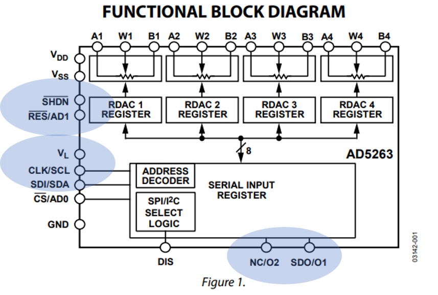
Every channel has one quad-trimmer chip, the AD5263 datasheet, to set the positive and negative bias applied to the load resitor in simmetric way. A scheme of the AD5263 is in figure Figure_Trimmer_AD5263.
The bias channels are 2 to allow to power in asymmetric way the 2 OAs: from +5 V up to +30 V and -5 V the OA for positive generation and from -5 V down to -30 V and +5 V the OA for negative generation of the bias. The amount of generating bias depends on the value of the pair of trimmers, coarse and fine, used at the input of each channel. The function to use is detector_scrittura_lettura_trimmer_bias() (refer to the Trimmer page for datail). Here an example:
From the example above we can extract 2 important rules. The first is the selection of the trimmer to use that can be done by the definitions, the value of the definition is its bullet:
The second regards the value that the trimmers should take. The middle value is at 128. The coarse trimmer has a negative gain so for positive output voltages the trimmer must take values smaller than 128, the inverse happens for negative output volatges.
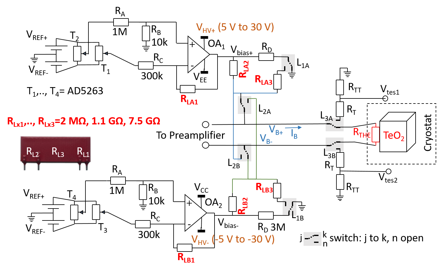
Considering the present hw setting we expect that the wiper, as a consequence of the trimmer attenuation (1k + 1k with the 20k trimmer, detector_trimmer_attenuation_x_1000), a step of about 35 mV. This gives, at the OA output a valu of (the gain is 2M / 270k, detector_OA_inverting_gain_x_1000) 0.2604 V per step.
Now the effect of the fine trimmer, starting with an example:
This trimmer has an attenuation at its output of 101 ( 10K over 1M, its inverse is this: detector_fine_trimmer_attenuation). It is applied to the non-inevrting input of the OA and therefore, its gain is one unit larger than that for the coarse gain (= 2M/270K +1, detector_OA_non_inverting_gain_x_1000). Important: for obatining a positive variation of the output voltage the trimmer value must exceed 128, the opposit for obtaining a negative output voltage.
Every wiper step is expected one hundred smaller than before, or 0.378 mV, while the OA output 2.96 mV per step.
Summary:
| Reading node | Detector bias slope | trimmer /gain |
|---|---|---|
| Bias positive | corse: 0.264 V/step | Detector_trimmer_coarse_bias_pos / negative gain |
| fine: 2.99 mV/step | Detector_trimmer_fine_bias_pos / positive gain | |
| Bias Negative | corse: 0.2604 V/step | Detector_trimmer_coarse_bias_neg /negative gain |
| fine: 2.99 mV/step | Detector_trimmer_fine_bias_neg / positive gain |
Every channel can have adjusted its detector bias with 4 trimmers. The bias is given differential and the positive value equals the absolute negative value. For each branch 2 trimmers are dedicated, the MS 8 bits and the LS 8 bits for each. The resolution is almost 16 bits. The content of each trimmer is in the matrix 12 x 4 contenuto_trimmer_detector[12][4]. There is another vector where the content of the target voltage to be set, in mV, are stored. This is the Detector_bias_target[12]. In both the matrix and the vector the positions are 12 to account for the lower and upper board.
When we need to set a bias we have to consider 2 instructions. The first allows to set the target voltage for each channels. This voltage can be the same or different for each channel. The function to do this is instr_detector_Vbias_we_want_to_set_function():
The bias, stored in the first 2 Bytes of the instruction data received, is applied to the channel(s) for which there is a "1" in the corresponding position at Byte6.
After that the target bias have been set it must be adjusted. This can be done by calling the function instr_Vbias_to_be_set_function(). These 2 commands are called in sequence over the CAN.
Trimmer contents can be readback with the CAN command da instr_detector_scrittura_lettura_trimmer_bias.
The approach to the bias setting considers independent the positive and negative branches of the bias, and avoids suddend voltages changes typical of the Successive Aapproximation procedure.
One of the OA feedback resistances and the load resistances have a good relative matching, but a few % of absolute matching. There are 2 fed backed OAs, Figure_detector_bias_setup, and, to minimize common mode settings, the bias for them is provided in an independent way and the detector resistances, RLxy in Figure_detector_bias_setup are calibrated.
br
The branch that provides the positive bias, VHV+, or more generically called Vbias, is supplied from -5 V up to 30 V, while the that providing the negative bias, VHV-, or more generically called Vbias, is supplied from +5 V down to -30 V.
The trimmers are biased from a precise pair of ±5 V and the setting of the wiper is independent from the OA power supplies.
The resistance, hence the slopes at the wipers, are previously calibrated and stored in the preamplifier EPROM. If calibration is not already provided it is measured, once, before the bias setting.
The knowledge of the slope is important to limit the use of the Successive Approxiamtion Registre, SAR, technique. The first step for setting the bias is to calculate the gues value for the trimmer. Then the residual error is measured and the SAR is applied to 2 or 3 bits only. This avoid the first steps of the classical SAR that consist of try with half the full scale of the ouput value, that can be 15 V even if the bias to apply is a few hundreds of mV.
The adjusting is done by a function that has embedded 2 other static functions. They are:
The codes for managing the bias are:
 unimib