 |
CROSS Technical Documentation User Manual and Technical Doc.
INFN Milano Bicocca
|
|
CROSS Technical Documentation User Manual and Technical Doc.
INFN Milano Bicocca
|
ADC/Mux ADG1408 description page
SUMMARY:
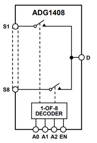
This chip is the ADG1408 (ADG1408 datasheet). 2 ADG1408 are on the mainobard and 8 are present on the postmainboard.
Thre are 2 ADG1408 chips on the board whose scheme is in figure Figure_Analog_mux. Each one allows to multiplex 8 analog inputs into one ouput. To select the input 4 signals are needed. The chip select that, for this chip, is active high and 3 parallel lines that codify the selected inpt. Once this is done, the output is available to be measured from the ADC. The series resistance of the chip is smaller than 10 Ω and 100 Ω are connected in series to the ouput for protecion.
To manage the chip there is only one function: Analog_mux_line_to_select_deselect( uint8_t scheda_su_scheda_giu, uint8_t line_to_select, uint8_t select_1_deselect_0) that is called 2 times in measurement. First it needs to activate the output and the parameter select_1_deselect_0 is 1. line_to_select is the line to select according to the following list, where the numbers on the left are the code to pass, and the definition on the right of the numbers are their equivalent aliases:
Once the measurement is done the function is called again with the same parameters, except select_1_deselect_0 that must be 0 this time.
Here an example of use of Analog_mux_line_to_select_deselect():
Postmainboard has 2 ADCs dedicated each to one of the 2 connected mainboards. Nodes to measure are routed by 2 groups of 4 analog multiplexers. In this case chip select lines and selection lines are all provided by the microcontroller and some functions are available:
Configure_Reset_selection_port_analog_mux_ResIn_ADC_buffer() is called at startup to set the pins and set the mux's in idle mode. It alsosets the pins for the switch put in series to the resistors at the ADC buffer input. The aim of this switch is to set this equivalent impedance to infinite value when the node voltage to measure is connected. Due to the fact that an attenuation is needed to avoid the rails the switches are always maintained in the closed state.
Analog_mux_line_to_select_deselect_for_postmainboard(), needs to know the mainboard to manage by scheda_su_scheda_giu, the node to measure by line_to_select and the setting of the path of the node to the ADC and is disconnession, by select_1_deselect_0. line_to_select are those listed at lista_nodi.
On the postamainboard there are 8 analog multiplexers, 2 groups of 4 for each connected mainboard. The multiplexers have simmetrical connections. To individuate an input line the syntax is: bits 0 to 3 are common to all the MUXs and select one of the input analog lines; bits 4 to 5 are the address for the chips select for the 2 groups of 4 MUXs. The selection of the MUX group is trhough the board_up_down. To select the lines a vector is dedicated to this. It is ADC_node_map[]:
The codes for mamnaging the mux are:
 unimib